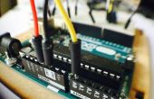
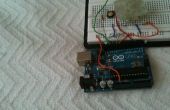
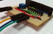
Stap 5: Controleren uw Module

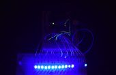
Zodra de module wordt gedaan kunt u de voltooide module met behulp van deze eenvoudige code controleren. De code geeft een led chaser en enkele andere interessante patronen. Deze code wordt in principe gemaakt voor het controleren van de module en ervoor te zorgen het werkt perfect.
CODE:
int data = 11; int clock = 12; int latch = 8; // the animation sequence for the LED display // first column is the LED status in binary form, second column is the timing in milliseconds byte patterns[48] = { B00000001, 100, B00000010, 100, B00000100, 100, B00001000, 100, B00010000, 100, B00100000, 100, B01000000, 100, B10000000, 100, B01000000, 100, B00100000, 100, B00010000, 100, B00001000, 100, B00000100, 100, B00000010, 100, B00000001, 100, B00011000, 200, B00100100, 200, B01000010, 200, B10000001, 200, B01000010, 200, B10100101, 200, B01011010, 200, B00100100, 200, B00011000, 200 }; // variables used for status int pattern_index = 0; int pattern_count = sizeof(patterns) / 2; void setup() { // setup the serial output if needed Serial.begin(9600); // define the pin modes pinMode( data, OUTPUT); pinMode(clock, OUTPUT); pinMode(latch, OUTPUT); } void loop() { // activate the patterns digitalWrite(latch, LOW); shiftOut(data, clock, MSBFIRST, patterns[pattern_index*2]); digitalWrite(latch, HIGH); // delay for the timing delay(patterns[(pattern_index*2) + 1]); // move to the next animation step pattern_index ++; // if we're at the end of the animation loop, reset and start again if (pattern_index > pattern_count) pattern_index = 0; } Als alles goed gaat dan zul je dezelfde output als weergegeven in de bepaalde video. In de volgende stap die ik zal tonen u hoe te daisy chain hen en de code voor het beheersen van de 24 + uitgangen met behulp van slechts 3 pinnen van de Arduino.
