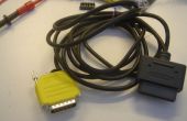
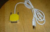
Stap 8: VPKB kabel

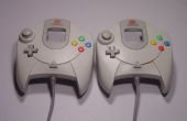
DREAMCAST Looking at controller end that plugs into the Dreamcast ___________ | 5 3 1 | \ 4 2 / --------- Pin Description Standard Wire Color 1 Serial A red 2 +5v blue 3 GND black 4 sense green 5 Serial B white Line 4, 'sense', is connected to ground in the controller. The Dreamcast uses this line to detect when there is a controller in place. Since we can connect it to ground inside the UPCB console cable hood, there is no need to connect this to the UPCB itself. To make a UPCB cable for the Dreamcast Piggyback, match up pins like this: D-Sub 15 Pin GC Pin 1 3 (GND) 2 Low 3 Low 4 High 5 High 6 Low 7 Low 8 2 (+5v) 9 NC - Not connected to anything 10 High 11 High 12 NC - Not connected to anything 13 1 (Serial A) 14 5 (Serial B) 15 Low You'll want to also solder in the 'sense' line to any one of the 'Low' lines. I soldered mine into 15 along with the little jumper wire that connected it to the rest of the 'Low' lines.
Bedrading van de Dreamcast Piggyback is kabel niet anders dan de bedrading van een andere kabel van de VPKB. Sluit alle van de hoge en lage pinnen, sluit de draden van de kabel zelf, en je bent klaar. Kijk dan op de andere twee Instructables op het maken van een kabel van de VPKB:
Hoe te bouwen van een consolekabel voor de universele PCB.
