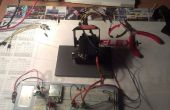
Ik schrijf dit zodat ik me herinneren hoe dat kan te doen dit laatste. Dit is een hack ik een paar jaar geleden en net trok uit de kast om opnieuw te gebruiken.
BACKROUND
Het is gebruikelijk dat u zou willen opslaan van de gegevens van een versnellingsmeter met een apparaat dat is klein. Ik ben met behulp van twee boards uit Spark fun; Open Log, en MMA8452 Breakout (dwz versnellingsmeter, zoals in uw smartphone).
De MMA8452 breakout board is een low-cost 3-assige versnellingsmeter gemonteerd op een kleine printplaat. De kop bevat de mededeling pinnen (I2C (denk ik)). Er zijn voorbeelden van hoe verbinding en gebruik deze met een arduino ontwikkeling boord.
IDEE
De planken logboek openen is in feite een arduino met een microSD-kaartslot gekoppeld. De arduino seriële gegevens worden ontvangen van de TX/RX-lijnen en slaat dit op de microSD-kaart. De pinnen haalde de kop zijn enkel wat u nodig hebt om te koppelen aan een arduino mini - zodat het beoogde gebruik is om dit te gebruiken om te lezen wat output van een ander circuit van de arduino.
DRADEN
Dus als u alleen wilt lezen en sla de gegevens van de versnellingsmeter, logisch om het rechtstreeks aan de datalogger draad. Je hoeft alleen om erachter te komen welke pinnen gaan waar...
MMA8452: OpenLog(atmega328) gelijkwaardig pin met behulp van de Arduino IDE
3,3 v---Vcc op kop
SDA---Pin 27 atmega 328---A4 (gele draad in de foto)
SCL---Pin 28 op atmega 328---A5 (witte draad in de foto)
GND---GND
Opmerking: arduino pinout diagram http://forum.arduino.cc/index.php?topic=132130.0
atmegaTQFP

Het logboek openen met een 3,3 v Program FTDI Basic. Allermeest naar de pinnen sluit rechtstreeks van koptekst op Koptekst--behalve u hoeft te verwisselen van de TX/RX-lijnen. Dus gaat OpenLogTXO naar FTDI_RXI.
Hier is de bedrading
OpenLog FTDI Basic
BLK---BLK
GND---GND
VCC---3,3 v
TXO---RXI (niet dwars door)
RXI---TXO (niet over straat.)
GND---GND
niet gebruikt---BLK
CODE - bibliotheek nodig
De bibliotheek moet u voor de versnellingsmeter:
https://github.com/Sparkfun/MMA8452_Accelerometer/...
Zet het dossier in de de bibliotheken file in de map van het schetsboek. Vind je het schetsboek, op arduino IDE, Selecteer Bestand -> preferences en het is juist aan de bovenkant. Vervolgens arduino IDE sluit en opnieuw opent.
(veel info hier:)
https://Learn.Sparkfun.com/tutorials/mma8452q-Acce...
CODE - schrijft versnellingsmeter output naar SD-kaart.
Er is sommige zeer goede code voor gebruik met de open logger, op zal verhuren u sluiten bepaalde configuratieparameters wijzigen en nieuwe bestanden te maken, ik ben niet met behulp van dat recht nu. Eenvoudig toegevoegd de SD-kaart schrijven naar het voorbeeld van de elementaire versnellingsmeter. Dit is de catch - er moet worden bestand genaamd datalog.txt ON THE SD CARD. Dat is het bestand dat de gegevens gaat naar.
De code moet worden gekoppeld.
Het heet: MMA8452_Plus_SDLogger
LINKS:
https://github.com/Sparkfun/MMA8452_Accelerometer
https://github.com/Sparkfun/OpenLog
OPMERKING:
de code lijkt niet te worden uploaden... dus hier is als tekst.
versnellingsmeter plus data logger code / / /
gewijzigd door MPC Marc Cryan / / /
/* MMA8452Q Basic Example Code Nathan Seidle SparkFun Electronics November 5, 2012 License: This code is public domain but you buy me a beer if you use this and we meet someday (Beerware license). This example code shows how to read the X/Y/Z accelerations and basic functions of the MMA5842. It leaves out all the neat features this IC is capable of (tap, orientation, and inerrupts) and just displays X/Y/Z. See the advanced example code to see more features. Hardware setup: MMA8452 Breakout ------------ Arduino 3.3V --------------------- 3.3V SDA -------^^(330)^^------- A4 SCL -------^^(330)^^------- A5 GND ---------------------- GND The MMA8452 is 3.3V so we recommend using 330 or 1k resistors between a 5V Arduino and the MMA8452 breakout. The MMA8452 has built in pull-up resistors for I2C so you do not need additional pull-ups. */ #include <Wire.h> // Used for I2C// The SparkFun breakout board defaults to 1, set to 0 if SA0 jumper on the bottom of the board is set #define MMA8452_ADDRESS 0x1D // 0x1D if SA0 is high, 0x1C if low//Define a few of the registers that we will be accessing on the MMA8452 #define OUT_X_MSB 0x01 #define XYZ_DATA_CFG 0x0E #define WHO_AM_I 0x0D #define CTRL_REG1 0x2A #define GSCALE 2 // Sets full-scale range to +/-2, 4, or 8g. Used to calc real g values./////////datalogger #include <SD.h> // On the Ethernet Shield, CS is pin 4. Note that even if it's not// used as the CS pin, the hardware CS pin (10 on most Arduino boards,// 53 on the Mega) must be left as an output or the SD library// functions will not work.constint chipSelect = 10; /////////////////voidsetup() { Serial.begin(57600); Serial.println("MMA8452 Basic Example"); Wire.begin(); //Join the bus as a master initMMA8452(); //Test and intialize the MMA8452 ////////////SDLogger Serial.print("Initializing SD card..."); // make sure that the default chip select pin is set to // output, even if you don't use it: pinMode(10, OUTPUT); // see if the card is present and can be initialized: if (!SD.begin(chipSelect)) { Serial.println("Card failed, or not present"); // don't do anything more: return; } Serial.println("card initialized."); ///////////////////// } voidloop() { int accelCount[3]; // Stores the 12-bit signed value readAccelData(accelCount); // Read the x/y/z adc values // Now we'll calculate the accleration value into actual g's float accelG[3]; // Stores the real accel value in g's for (int i = 0 ; i < 3 ; i++) { accelG[i] = (float) accelCount[i] / ((1<<12)/(2*GSCALE)); // get actual g value, this depends on scale being set } // Print out values for (int i = 0 ; i < 3 ; i++) { Serial.print(accelG[i], 4); // Print g values Serial.print("\t"); // tabs in between axes } Serial.println(); ///////////data to SD card // open the file. note that only one file can be open at a time, // so you have to close this one before opening another. File dataFile = SD.open("datalog.txt", FILE_WRITE); // if the file is available, write to it: if (dataFile) { for (int i = 0 ; i < 3 ; i++) { dataFile.print(accelG[i], 4); // Print g values dataFile.print("\t"); // tabs in between axes dataFile.close(); } } // if the file isn't open, pop up an error: else { Serial.println("error opening datalog.txt"); } ////////////// delay(10); // Delay here for visibility } void readAccelData(int *destination) { byte rawData[6]; // x/y/z accel register data stored here readRegisters(OUT_X_MSB, 6, rawData); // Read the six raw data registers into data array // Loop to calculate 12-bit ADC and g value for each axis for(int i = 0; i < 3 ; i++) { int gCount = (rawData[i*2] << 8) | rawData[(i*2)+1]; //Combine the two 8 bit registers into one 12-bit number gCount >>= 4; //The registers are left align, here we right align the 12-bit integer // If the number is negative, we have to make it so manually (no 12-bit data type) if (rawData[i*2] > 0x7F) { gCount = ~gCount + 1; gCount *= -1; // Transform into negative 2's complement # } destination[i] = gCount; //Record this gCount into the 3 int array } } // Initialize the MMA8452 registers // See the many application notes for more info on setting all of these registers:// http://www.freescale.com/webapp/sps/site/prod_summary.jsp?code=MMA8452Qvoid initMMA8452() { byte c = readRegister(WHO_AM_I); // Read WHO_AM_I register if (c == 0x2A) // WHO_AM_I should always be 0x2A { Serial.println("MMA8452Q is online..."); } else { Serial.print("Could not connect to MMA8452Q: 0x"); Serial.println(c, HEX); while(1) ; // Loop forever if communication doesn't happen } MMA8452Standby(); // Must be in standby to change registers // Set up the full scale range to 2, 4, or 8g. byte fsr = GSCALE; if(fsr > 8) fsr = 8; //Easy error check fsr >>= 2; // Neat trick, see page 22. 00 = 2G, 01 = 4A, 10 = 8G writeRegister(XYZ_DATA_CFG, fsr); //The default data rate is 800Hz and we don't modify it in this example code MMA8452Active(); // Set to active to start reading } // Sets the MMA8452 to standby mode. It must be in standby to change most register settingsvoid MMA8452Standby() { byte c = readRegister(CTRL_REG1); writeRegister(CTRL_REG1, c & ~(0x01)); //Clear the active bit to go into standby } // Sets the MMA8452 to active mode. Needs to be in this mode to output datavoid MMA8452Active() { byte c = readRegister(CTRL_REG1); writeRegister(CTRL_REG1, c | 0x01); //Set the active bit to begin detection } // Read bytesToRead sequentially, starting at addressToRead into the dest byte arrayvoid readRegisters(byte addressToRead, int bytesToRead, byte * dest) { Wire.beginTransmission(MMA8452_ADDRESS); Wire.write(addressToRead); Wire.endTransmission(false); //endTransmission but keep the connection active Wire.requestFrom(MMA8452_ADDRESS, bytesToRead); //Ask for bytes, once done, bus is released by default while(Wire.available() < bytesToRead); //Hang out until we get the # of bytes we expect for(int x = 0 ; x < bytesToRead ; x++) dest[x] = Wire.read(); } // Read a single byte from addressToRead and return it as a bytebyte readRegister(byte addressToRead) { Wire.beginTransmission(MMA8452_ADDRESS); Wire.write(addressToRead); Wire.endTransmission(false); //endTransmission but keep the connection active Wire.requestFrom(MMA8452_ADDRESS, 1); //Ask for 1 byte, once done, bus is released by default while(!Wire.available()) ; //Wait for the data to come back returnWire.read(); //Return this one byte } // Writes a single byte (dataToWrite) into addressToWritevoid writeRegister(byte addressToWrite, byte dataToWrite) { Wire.beginTransmission(MMA8452_ADDRESS); Wire.write(addressToWrite); Wire.write(dataToWrite); Wire.endTransmission(); //Stop transmitting }


