Stap 3: Switch en LED en het gebruik van pin bank overleden

Bank D controleert pinnen 0 - 7, maar PIN 0 en 1 worden gebruikt voor seriële communicatie. Meeste Arduino liefhebbers probeer niet deze pinnen voor iets anders gebruiken. Dingen kunnen raar als je met deze pinnen knoeien krijgen. Dus voor de veiligheid is het beste voor het behoud van de waarden van bit 0 en 1 in de registers van DDRD en PORTD. Dit vereist het gebruik van logische AND en/of opdrachten.
Elk journaal is 8 bits 0 tot en met 7 van rechts naar links genummerd. Bit 0 is 2 ^ 0, bit 1 is 2 ^ 1, enz.
Een logische OR vergelijkt twee bytes bit voor bit en het resultaat is 1 als beide of het aantal bytes is 1, zo niet het resultaat is 0.
De verticale streep (|) is het symbool voor een logische OR.
Hier is een waarheidstabel voor een logische OR:
0 | 0 = 0 0 | 1 = 1 1 | 0 = 1 1 | 1 = 1
So if we OR 11001100 Against 00111100 The result will be 11111100
.
Een logische en vergelijkt twee bytes bit voor bit en het resultaat is 1 alleen als beide bits 1 zijn.
Het en-teken (&) is het symbool voor een logische AND.
Hier is een waarheidstabel voor een logische en:
0 & 0 = 0 0 & 1 = 0 1 & 0 = 0 1 & 1 = 1
So if we AND 11001100 Against 00111100 The result will be 00001100
Oog op het behoud van een beetje u kunnen OR tegen 0 of en het tegen 1.
Volg samen met de documentatie in het programma om te zien hoe dit werkt.
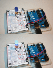
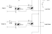
Bouwen van het circuit in het diagram weergegeven, zult u moeten:
- Arduino
- Breadboard
- LED
- Weerstand, 330-560 Ohm
- Jumper draden
Kopieer dit programma naar de Arduino IDE en uploaden naar je Arduino:
/********************************************************* * Demonstration using bank D pins 0 - 7 and preserving the * values of pins 0 and 1 in the DDRD and PORTD registers. * * The anode of an LED is connected to pin 7 with * a resistor in series connected to ground. * * A pushbutton switch is connected to pin 2 and ground * and uses the internal pull-up resistor. * * The LED lights when the button is pressed. * *********************************************************/ /********************************************** * setup() function **********************************************/ void setup() { // Set pin 2 to input and pin 7 to output // while maintaining the state of pins 0 and 1. // We don't care what happens to 3 - 6. DDRD = DDRD | B10000000; // The "|" means a logical OR. // We now know that bit 7 is high. // And we know bits 0 and 1 are preserved. // But we still are not sure of bit two. DDRD = DDRD & B10000011; // We do a logical AND, now we know the status of all the bits. // A logical OR against zero or a logical AND against one // will not change the status of a bit. // This preserved the status of bits 7, 1, and 0. // Since bit 2 was ANDed against 0 we know that it is now clear. // The DDRD register is now where we want it. // Now we need to get the PORTD register set the way we want it. PORTD = PORTD & B00000011; // Bits 0 and 1 are preserved, all others are off. PORTD = PORTD | B00000100; // Bits 7 is off, the initial state of the LED. // Bit 2 is on, because pin 2 is an input turning it's bit // on in PORTD turns on the internal pull-up resistor. } /********************************************** * loop() function **********************************************/ void loop() { // Read the PIND register. int button = PIND; // you now have the values of all eight pins in the PIND register // contained in a variable. The only pin we care about is pin 2. // So we do a logical AND on the button variable to isolate the // bit we want. button = button & B00000100; // Because of the internal pull-up resistor the pin will be high // if the button is not pressed, and low if it is. // So button will return either 2^2 (4) or zero if it is pressed. PORTD = PORTD & B00000111; // Turn LED off, and preserve bits 0 - 2. if(button == 0) { PORTD = PORTD | B10000000; // turn LED on, and preserve bits 0 - 2. } } De opdracht digitalWrite() zal vertragen een programma veel in een lus, maar de opdracht pinMode() is normaal gesproken alleen gebruikt in de Setup-functie en eenmalig uit te voeren. het bovenstaande programma zal net zo goed uitvoeren als u een meer standaard Setup-functie, zoals dit gebruiken:
setup() { pinMode(7, OUTPUT); pinMode(2, INPUT_PULLUP; } Terwijl met behulp van het register van DDRD niet nodig dat het is leuk om te begrijpen hoe het en de logische operaties werken is.
