Stap 5: Program de Controller
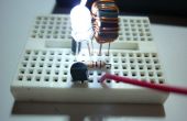
De code voor het project is echt heel klein. Code gecompileerd met AVRGCC. De code is geprogrammeerd in de controller via de ISP-connector op de controller PCB./ * Code voor een trillende kaars project * /
/ * Verbind een 1-W geel/Warm witte LED op * /
/ * Pin 2 - PB3 <--50 Ohm R--> LED Cathode * /
/ * Pin 3 - PB4 <--50 Ohm R--> LED Cathode * /
/ * Pin 5 - PB0 <--50 Ohm R--> LED Cathode * /
/ * Pin 6 - PB1 <--50 Ohm R--> LED Cathode * /
/ * Pin 7 - PB2 <--50 Ohm R--> LED Cathode * /
/ * LED Anode naar Vcc
/ * Ingesteld max stroom om 30 mA voor elke LED * /
/ * LFSR Bron: http://en.wikipedia.org/wiki/Linear_feedback_shift_register * /
#include < avr/io.h >
#include < avr/delay.h >
Main()
{
niet-ondertekende lange lfsr = 1;
unsigned char temp;
DDRB = 255;
for(;;)
{
LFSR = (lfsr >> 1) (-(lfsr & 1u) & 0xd0000001u); / * kranen 32 31 29 1 * /
Temp = (unsigned char) lfsr;
DDRB = ~ temp;
PORTB = temp;
Temp = (unsigned char) (lfsr >> 24);
_delay_loop_2 (temp << 7);
}
}
